Configure PAJ PET Finder 4G for Traccar


@GPS4PETS Is the debug USB working also with FlashTool (to save and restore FW)?

Hello,
I own a PAJ Power Finder Online with micro USB.
But there ist no connection with a TTL 2 USB Converter.
Can someone help me?
Thank You very much

@snoopy152_de there is no need to use usb2ttl on this one. Just use USB data cable and get the drivers installed and you'll see 2 serial devices
@mcpower, thank you, for your reply. I've tried these on 2 devices and several data cables but no luck. Windows won't recognize any devices.
With the Power Finder 4G and USB C, this happens immediately.

I modified the USB-A/4-pin clamp cable of my PAJ Pet Finder 4G according to GPS4PETS' instructions. In my case, the device does not emit any messages. I tried switching RX and TX already. The device echoes my input though. Do you have any ideas what I could do? I'm happy to dismantle the device. Thanks in advance!

Hello,
I traced the thread and admire the work done.
I bought the tracker to learn something, but after uploading the FW OTA, the GPS didn't. The tracker was a full day under the open sky. It sends data to Traccar. I've analyzed the logs, and the coordinates are 0. Do you have any ideas what might be wrong with the tracker's position? Doesn't this FW handle NEMA messages well?
PajPet gps tracker
P-Finder 4G-V2.0.20250527
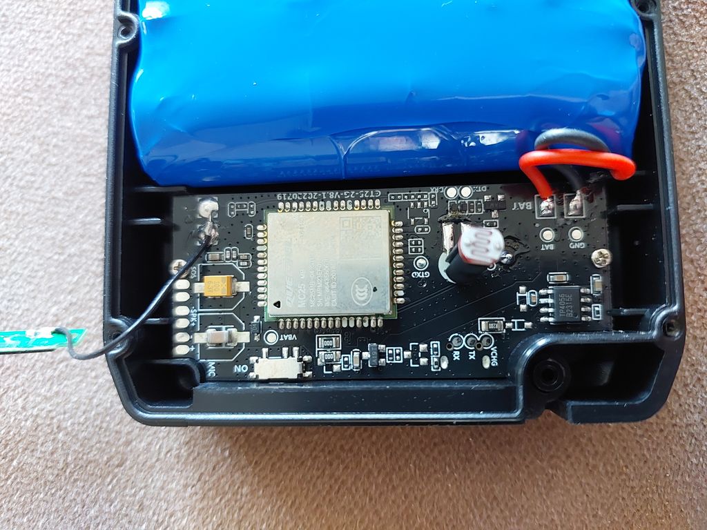
Hi @mjg, I have the same PCB. How did you manage to do the FW OTA? I found three UART ports on the PCB. One sends observed wifi mac adresses periodically, the second emits NEMA messages and the third prints the "Bye Bye bootloader" message. None of these ports appear to accept any commands and only the third port echoes my input. I will update the thread once I find out more about the device.
Hi Hans,
I also tried to sniff communication with similar results.
I changed SIM card and send SMS command to download firmware from previous post.
Ok, I think I know why some of us don't get responses on the UART interface with tools like screen, minicom or tio. I gave SSCOM a try and it magically worked.
I noticed that SSCOM sends \r\n before and after each command. The tools that I tried (screen, minicom and tio) only send \r by default. So I used the map option in tio to make it send \r\n as well. I started it like this:
tio --map ONLCRNL /dev/ttyUSB0
Before sending any command I press ENTER once just to clear any garbage that may have been sent over the wire earlier. The UART port I used is labeled URX, UTX, GND on the P-Finder 4G-V2.0-20250527 board.
Once I had set everything up, I was able to send the command AT%TEST=START and it gave me a proper response:
AT%TEST=START
*************************************************************

1. ID:9091[REDACTED]

2. VER:P-Finder 4G(70G_V5.0) 25/05/17  SDK_1.011.042

3. IP:prod-service2.paj-gps.com-9077 APN:wsim

4. PWR:OFF V:0

5. SIM:PASS, 1

6. GSM: 6

7. GPRS:FAIL ON

8. GPS:FAIL-ON 04-01-00--V

IMEI:86[REDACTED]

PN:S2-10AZT

*************************************************************
Side note: The AT command reference manual (A76XX-Series_AT_Command_Manual_V1.06-4.pdf) appears to be inaccurate as it clearly states that the chip expects only \r/<CR> after the command rather than \r\n/<CR><LF>.
The "AT" or "at" or "aT" or "At" prefix must be included at the beginning of each command line (except A/ and +++), and the character
<CR>is used to finish a command line so as to issue the command line to the module.

Hi
can anyone tell me where is UART port, because i can see two different RX an TX pins
I don't know that board, mine is different. You can either try them both (be sure to use a 3.3V TTL converter) or you can Google the datasheet of the chip and then trace the correct pins from the chip to the test pads using a multimeter.
Don't you have a USB-C port on the device? If so, you probably should see the serial devices when connecting the USB cable to a computer. In that case, you don't need to connect a TTL converter to the PCB manually.
@hansacker
Can you show what data is sent to prod-service2.paj-gps.com
@newvol: As far as I know, I don't see this on my interface. I tried attaching a USB cable to GND/DM/DP/VBUS port on the PCB of the Pet Finder 4G but my computer did not recognize a USB device. I was hoping to be able to sniff the traffic as GPS4PETS pointed out. Not exactly sure if he took some extra steps that I am not aware of..
I managed to change the backend and I pointed the tracker to the traccar demo server like this:
AT%TEST=SMS[][IP 188.245.151.94 5013]
Mine is sending the h02 protocol and I think this is what others have reported as well for the stock firmware. I was even able to send custom commands back to the device (toggle light). Thanks to everyone in this thread for sharing!!
setting upload interval
FREQ,515118,INTERVAL_IN_SECONDS