Hi everyone,
I am trying to repurpose a Queclink GB130MG GPS tracker (originally provisioned by Rewire Security. They have ceased to provide coverage in my area), to work with a local Digicel Samoa SIM card and point it to my own tracking server. Rewire Security will not provide the configuration password, and because I am located in Samoa, I do not have access to official Queclink pogo-pin cradles or proprietary programming cables.
Hardware Details:
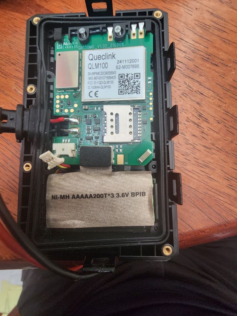
• Tracker Model: Queclink GB130MG (PCB marked GB130MG_V1.02_210908)
• Cellular Module: Queclink QLM100 (LTE Cat M1 / NB2)
• Internal Battery: 3.6V Ni-MH (NI-MH AAAAA200T*3) via 3-pin JST connector
What I am looking for help with:
- 5-Pad UART Pinout: On the right-hand edge of the PCB (next to the QLM100 shield and SIM slot), there is a vertical row of 5 gold test pads (plus 3 pads on the left edge). Has anyone mapped out which of these 5 pads are GND, TX, RX, and what logic voltage the QLM100 uses (1.8V vs. 3.3V)? I plan to solder thin wires from a standard USB-to-TTL serial adapter directly to these pads.
- Clearing/Bypassing the Reseller Password: Once I connect via serial UART using the Queclink Manage Tool on Windows, is there a known serial command, boot mode, or factory reset procedure to wipe the reseller configuration password on the GB130MG? (I am also testing if Bluetooth BLE is left open with default credentials).
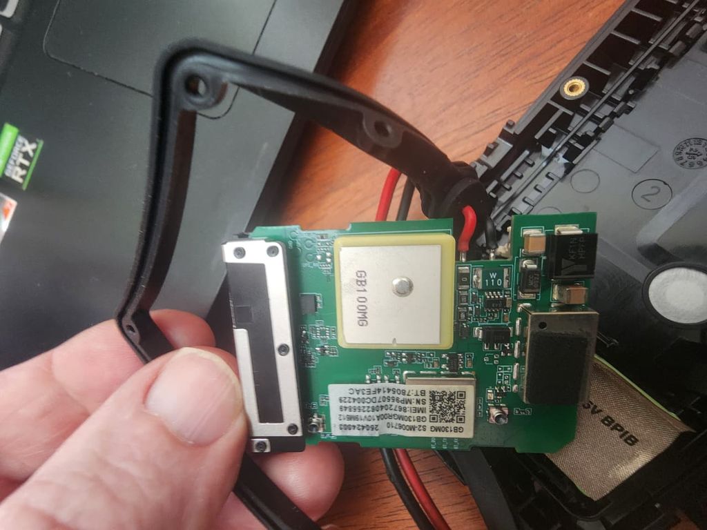
I have attached clear photos of both the front and back of the PCB. Any help identifying the exact TX/RX pads or sharing reset steps for this board would be greatly appreciated!

Hi everyone,
I am trying to repurpose a Queclink GB130MG GPS tracker (originally provisioned by Rewire Security. They have ceased to provide coverage in my area), to work with a local Digicel Samoa SIM card and point it to my own tracking server. Rewire Security will not provide the configuration password, and because I am located in Samoa, I do not have access to official Queclink pogo-pin cradles or proprietary programming cables.
Hardware Details:
• Tracker Model: Queclink GB130MG (PCB marked GB130MG_V1.02_210908)
• Cellular Module: Queclink QLM100 (LTE Cat M1 / NB2)
• Internal Battery: 3.6V Ni-MH (NI-MH AAAAA200T*3) via 3-pin JST connector
What I am looking for help with:
I have attached clear photos of both the front and back of the PCB. Any help identifying the exact TX/RX pads or sharing reset steps for this board would be greatly appreciated!